


This was a HOW-TO on the zx14ninja.com forum. It was posted by faz on 7/21/08.
I searched around and did not find a how-to thread on TRE installation (especially one with pictures), so I am writing this to help other new members here with this installation. Below I have tried to be as detailed as possible, but only reading the bold highlighted parts should give you an idea of what is involved.
I know this is old news for old timers here, but for a new person who just bought their ZX14, this might prove to be helpful.
Hope this helps a few people, and oh, use this instructions at your own risk.
This how-to is for the installation of TRE 008, but the 006A should be very much the same.
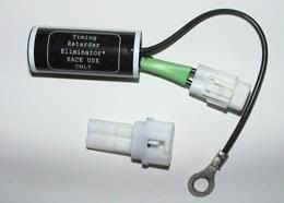
This is the TRE 008 package that you receive. As seen in the picture, it should come with an empty 2-pin connector housing.
Finding the GPS connector: On the left hand side of the bike, above sprocket cover near the white radiator overflow tank, you will find a green 4 pin GPS connector (Gear Position Sensor). That is the connector you will be working with.
Sit on the floor on the left hand side of the bike, and separate this connector.
The left hand side of the connector has a female housing (with male pins inside), and the wires from it are connected to the main wiring harness.
The right hand side of the connector has a male housing (with female pins inside), and the wires from it are connected to the GPS.
In order to install TRE, you will need access to the female housing portion of this connector (the left hand side one.)
In my case, the wire from the main harness leading to the female housing was twisted around the main harness, and didn't leave enough room/slack for me to work with the female housing, so I had to do some extra work:
The main harness is zip tied/clamped to the frame right behind the overflow tank:
- I had to remove the left hand side "foreman grill" cover.
- Undo that zip tie / clamp to give the main wiring harness a bit more room to play with.
- Then I had to to unwind the female housing wire from the main wiring harness just above the zip tie location. But, there was a catch: the main portion of the wire that goes to the female housing (that we are trying to unwind) also branches out to two other connectors as well. I had to separate/unplug those two connectors also, to be able to unwind all 3 connectors/wires at the same time.
- After unwinding the 3 connectors/wires from the main harness, I plugged the other two connectors right back in.
So now I had the female housing with some more slack/room to work with.
Two pins have to be pushed out of the female housing, these are pins that are connected to: (Green/Red) and (Black/Yellow) wires.
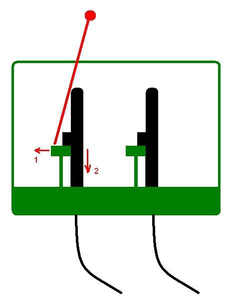
I made this drawing to give a visual idea of how the pins are locked in place, and what you need to do to unlock them before pushing them out. In this drawing, which is a side view of the connector, the green parts show the plastic housing and plastic tabs that are locking the pins in place. The pins are shown in black:
Looking from the above and into the female housing:
- I held the housing in my hand using the ring and pinky fingers.
- With my thumb/index fingers used a thick sewing needle to push the green tab out and away from the pin.
- While using a small screw driver in my other hand to gently push the metal pin down.
- The gently part is the key here. If the green tab has not cleared the pin completely, the pin can bend if you push too hard.... so be patient and gentle.
Once the two pins were removed from the female housing, the rest of the female housing can be plugged back in.
These pins will now go into the empty housing that comes with the TRE. The orientation is important, and instructions from TRE say that black/yellow wire should go into the slot marked by a black mark on the housing.
The diagram below shows how the whole setup fits together:
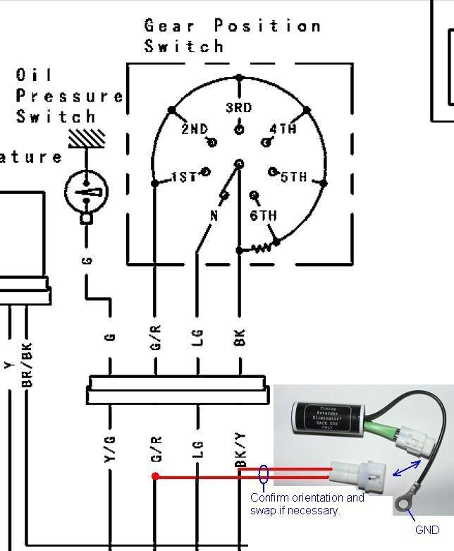
The ground treminal gets connected to a 8 mm bolt on front sprocket cover.
Once everything is done, you can do some cleanup (zip tie wires/etc. together), and go for a ride.
Alternatively
I went with the TRE option so that I don't cut the wires on my bike... I wanted to be able to go back to stock form if/when I wanted to. If you don't have any problems with cutting a wire on your bike, there is another nice how-to thread here that explains a 25 cent alternative to all of this:
https://zx14ninjaforum.com/messages.cfm?threadid=5DCDD2CB-1372-66AE-3BF0C5E1EDFF376D
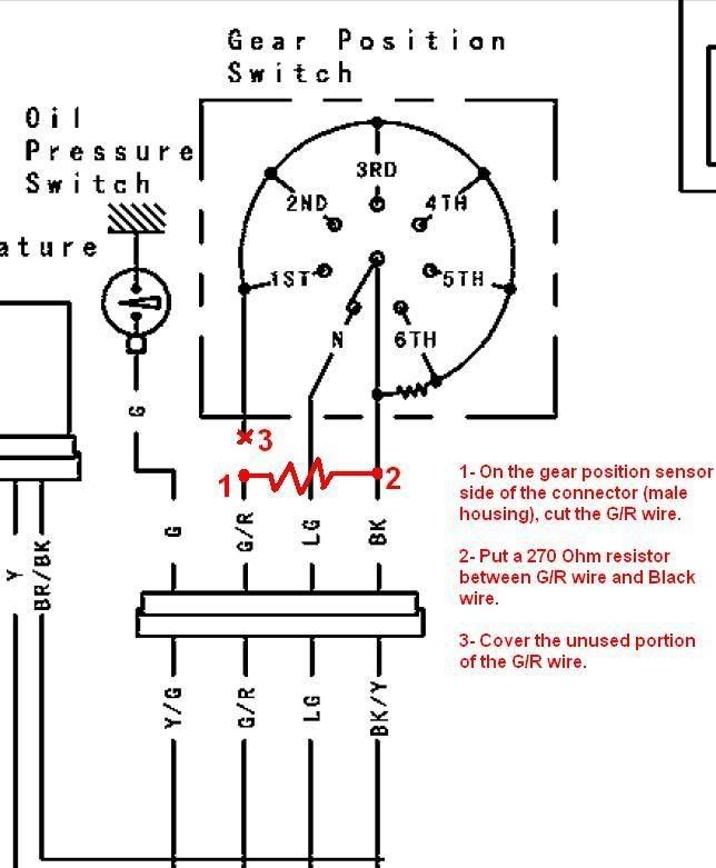
The above link basically describes how you can splice in a 220 (or 270 ohm) resistor into the wiring and achieve the same results as a TRE package bought for $50+. ![]()
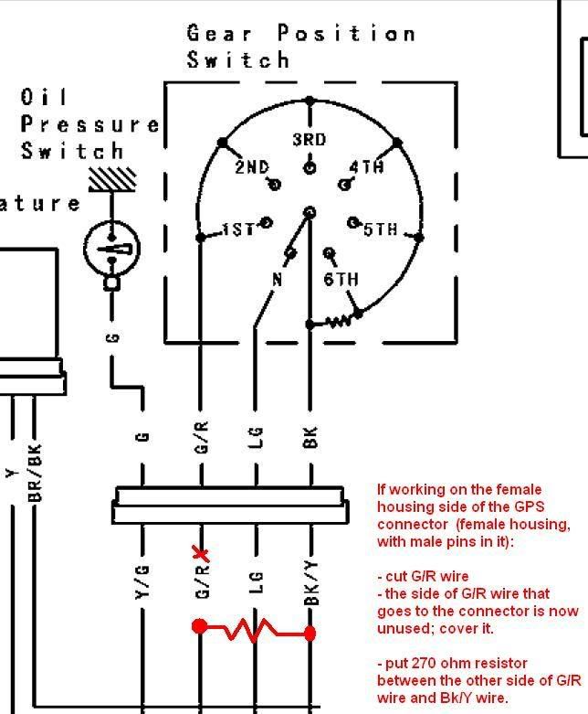
I put together the following two diagrams to help with that approach, if that is the way you prefer to go:
Please note: regardless of which side of the connector you choose to cut the green/red wire, the unused portion of the green/red wire becomes the portion that goes towards the gear position sensor near sprocket, and the used portion (which you should connect the resistor to) is the portion that goes towards to the main wiring harness.
_________________
Ride Safe!
* Last updated by: bgordon on 2/10/2009 @ 10:52 AM *