


Throttle Body Assembly Removal
The Throttle Body Assembly may be removed in order to replace or repair it. It may be removed just to make room to work on the top engine. When the Throttle Body Assembly is removed for a prolonged period of time, it is wise to cover the top and bottom of the bores with small plastic sheets secured by rubber bands. The inlets to the Throttle Body Holders should also be covered in the same way so that no dust or dirt can enter the engine.
Do not smoke while performing the procedure and prevent all open flame from being present. Expect gasoline to leak and be prepared to dry up spills immediately.
Do First:
Disconnect the fuel hose joint from the fuel pump see Fuel Line Removal, step 4).
Remove the lower ends of the throttle cables (see Throttle Cables Removal, steps 6, 7 and 8).
Disconnect the crankshaft sensor lead (see CRANKSHAFT SENSOR REMOVAL, GEN1, step 5).
Disconnect the throttle bodies subharness from the main wiring harness (see THROTTLE BODIES SUBHARNESS REMOVAL, step 2).
Remove INTAKE DUCTS, steps 1 through 6).
Tools
4mm hex tool
silicone lubricant
compressed air
rag
small sheets of plastic
12 small rubber bands
torque wrench
Removal
1. Remove the idle speed adjuster cable from the retainer clamps [B] on the clutch fluid line and fuel tank breather hose. 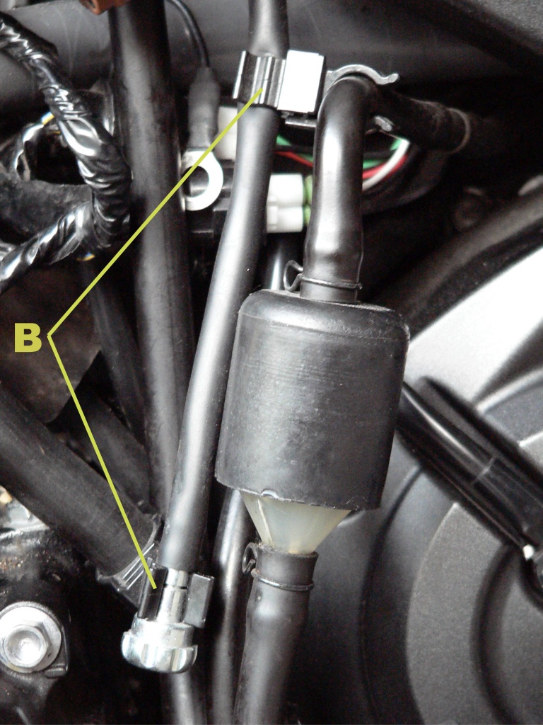
2. Use a 4mm hex tool to loosen the holder clamp bolts (circled in yellow, one on each side of the motorcycle) and free the clamps so that they are not stuck to the rubber the holders.
Do not remove the bolt or the clamp spacer tube (see photo, step 3 below) will fall out.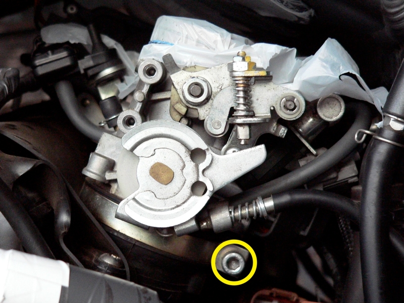
3. Before removing clamps, blow off areas around ducts and throttle body holders with compressed air and wash thoroughly with a rag moistened with silicone lubricant. Pay special attention to the valleys between the throttle body holders. Gravel accumulates there on top of the motor and it could be injurious to the engine if it were to fall into intakes. Also be careful to remove the dust which is attracted by the oil film that often is present on the rims of the holders. Clean the whole motor off with a damp rag to reduce the chance of any dust entering. 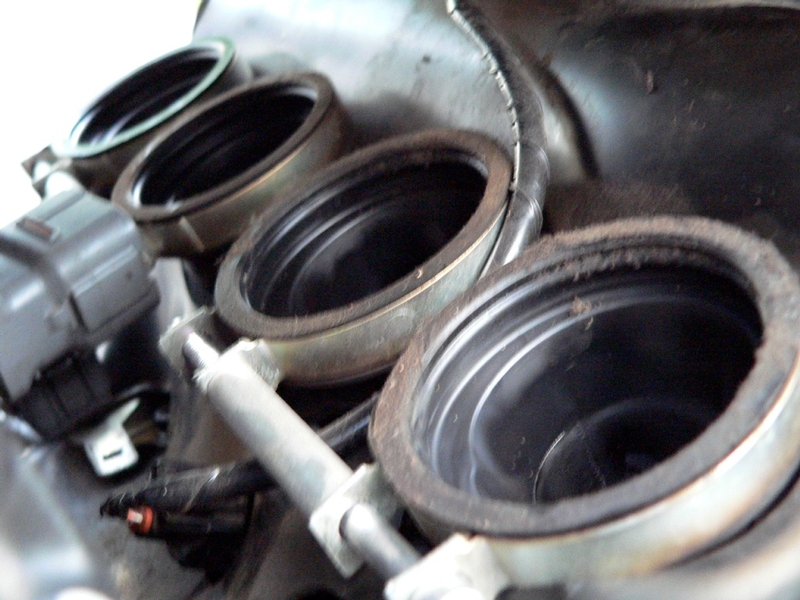
I neglected to clean my holders off well and this resulted in some of the dust that had accumulated falling into my intake. If any foreign matter falls into the intakes, they should be blown out with compressed air.
4. Rock the throttle bodies assembly forward and backward to loosen it from the holders.
5. Push the fuel hose forward from the fuel tank compartment a few inches to free up enough slack to allow the throttle bodies to be pulled out to the left. Do not kink the hose.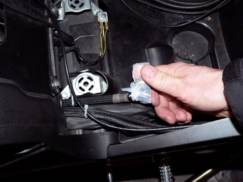
6. Lift the throttle bodies assembly up out of the holders and pull it to the left far enough that the fuel hose joint on the fuel rail may be easily reached.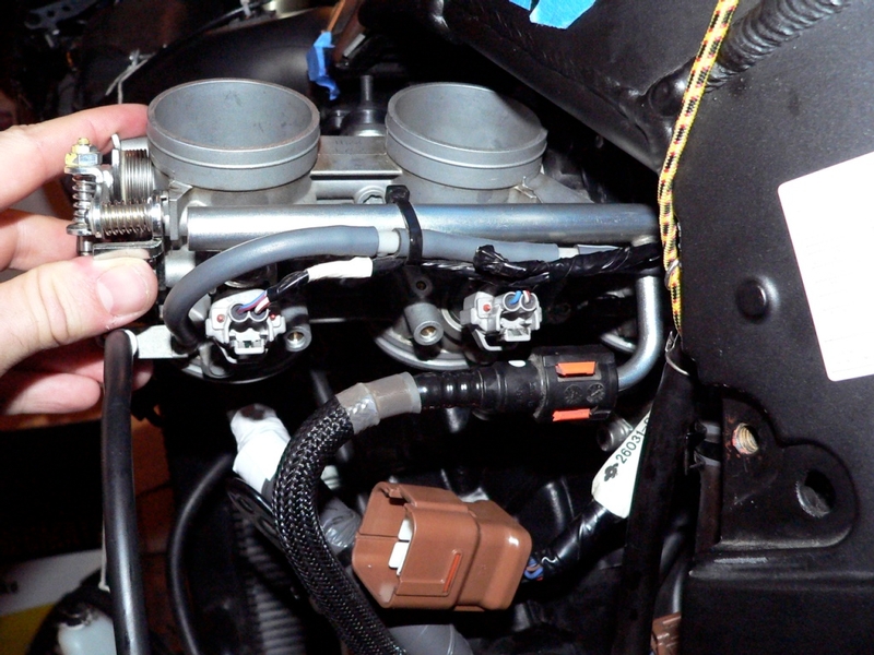
7. Remove the fuel hose joint from the fuel rail inlet tube (see steps 3 and 4 of Fuel Line Removal).
8. Pull the throttle body assembly out of the engine compartment to the left.
Cover the bottom of the throttle bores with plastic secured with a rubber band as was done to the top.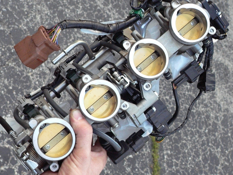
9. Cover throttle body assy holders with plastic and secure it with a rubber band.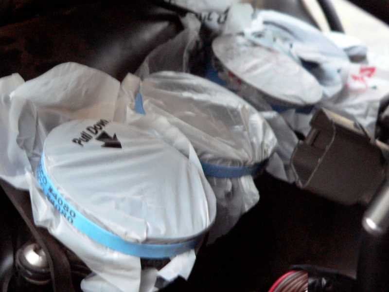
Installation
10. Place the throttle body holder clamps onto the throttle body holders with bolts situated to the back of throttle body holders.
The hex in the bolt head needs to be facing outward to the side so that it may be tightened with a wrench.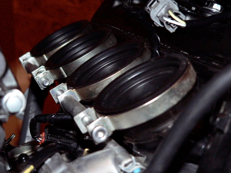
11. Remove the plastic dust covers from the top and bottom of the throttle bodies bores (step 8).
Use a finger tip to apply a film of silicone lube to the inside of the holders and the bottom outer ridge of the throttle bodies bores.
Place the throttle body assy halfway into the engine compartment so that the fuel delivery pipe is accessible (see step 6 of this tutorial).
Install the fuel line hose joint with the white dot to the delivery pipe of the fuel rail on the throttle bodies assembly (see steps 7 and 8 of Fuel Line Removal).
12. Remove the plastic from the throttle bodies assy holders and position the throttle body bores on top of the holders.
13. Apply silicone lubricant to the throttle bodies holders and bottoms of the bores.
Press the throttle body bores into place so that the ridge inside the throttle body holder interlocks between the two ridges at the bottom of each bore. There should be no ridge showing at all at the bottom of the bores. I worked the throttle body bores into the holders by rocking one side at a time forward and backward. Then repeated the process on the other side.
Check to see that the opposite side did not pop back out. 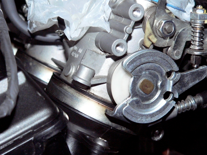
14. Torque the throttle bodies holder clamps using a 5mm hex key bit and a torque wrench.
Torque: throttle body holder clamps 18 in lbs
15. Rout the idle speed adjuster cable as shown and secure it into the black plastic
retainer clamps. 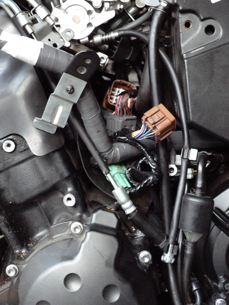
Connect and reinstall the throttle bodies sub harness lead to the main wiring harness (see THROTTLE BODIES SUBHARNESS REMOVAL, step 9 and 10).
Connect throttle cables to throttle bodies actuator.(see Throttle Cables Removal, step 14)
Connect the fuel hose joint to the fuel pump seeFuel Line Removal, step 8).
Install fuel tank (see Fuel Tank Removal, steps 7 through 10)
Connect the crankshaft sensor lead (see CRANKSHAFT SENSOR REMOVAL, GEN1, step 5).
Connect the battery negative cable(Battery Removal, step 2).
Install left side subframe (see Left side Subframe Removal Steps 8-14)
Install the Engine Coolant Reservoir (see, Engine Coolant Reservoir step 3).
* Last updated by: Rook on 12/25/2017 @ 4:05 PM *