Move Close
Welcome to zx14ninjaform.com!

You are not logged in.
New Topic Reply
Next Page

Page: 1

Previous Page

Thread: How To Load Maps and Overview of Power Commander 5 v1.0.6.4

Created on: 07/23/16 11:56 PM

Replies: 9

Rook


Rook's Gravatar

Joined: 03/28/09

Posts: 20579

How To Load Maps and Overview of Power Commander 5 v1.0.6.4
07/23/16 11:56 PM

How To Load Maps and Overview of Power Commander 5 v1.0.6.4

I will explain the purpose of all functions and displays of Power Commander 5 v1.0.6.4 in this tutorial. You may use this information to experiment and help acquaint yourself with the software. If you X out of selection boxes rather than clicking the OK button, the settings in your PCV will remain what they previously were. The steps that you should check and save changes if necessary are:

Step 23. Click Defaults > OK or select option(s) to create backup map files.
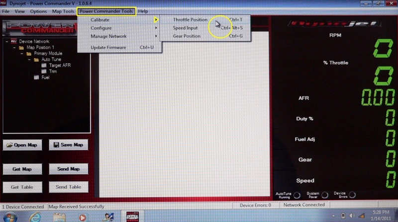
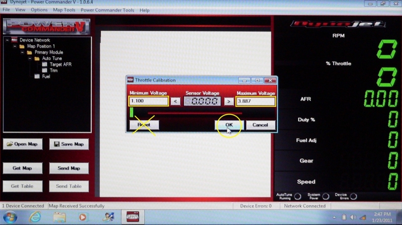
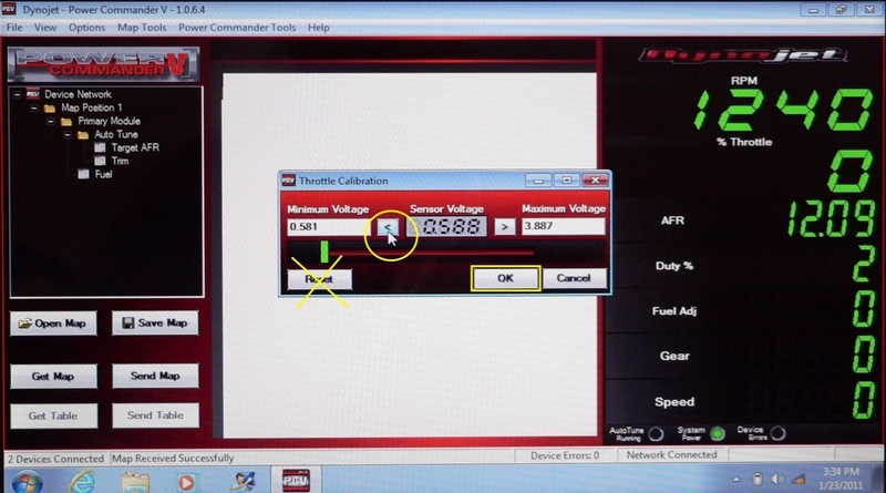
Step 27. TPS voltage and percentage calibration.
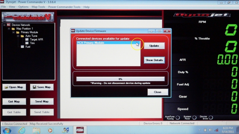
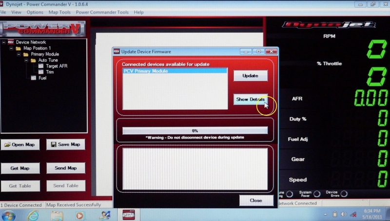
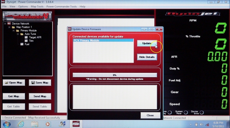
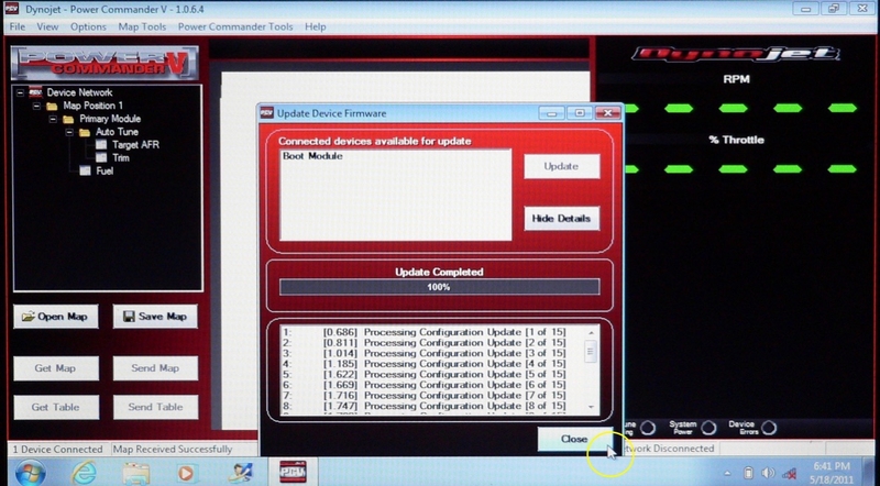
Step 36. Update firmware.

The process of loading maps is explained in detail but this tutorial is not meant to fully explain implementation of most other processes that may be executed with the software. I will address those processes in future tutorials where the auxiliary wiring, sensors and other devices required are also explained.

A laptop is the best computer to use PCV software with because a laptop is easy to bring to the bike. In some cases, you may want to carry the computer on the bike to make calibrations. A small laptop is best for this. I have a Gateway LT4010u notebook and it is the perfect size to velcro to the fuel tank cover while still being large enough to view and use while riding.

COMPUTER FOR TUNING

Downloading PCV Software To Your Computer
To download the most current version of Power Commander 5 software, go to powercommander.com

click the left hand picture of the race bike, ACCESS RACE READY, FUEL INJECTION MODULE SITE

from top menu, click DOWNLOADS

from listed items, click access downloads > Power Commander V

from listed items, find SOFTWARE, Power Commander V Software, 1.0.6.4
click file icon under Download

Retrieve file, Install Power Commander 5 v1.0.6.4.exe from your downloads and double click to begin the install to your PC computer (Power Commander software is not Mac compatible). I accepted all default settings clicking Continue in each box that came up and finally clicked Finish. There will be an Icon on the desktop to open the PC5 software.

Downloading Dynojet files is not difficult but you may use the following link for a more detailed description.

DOWNLOADING DYNOJET FILES

Power Commander 5 v 1.0.6.4 is the most current software as of 07-2016. This software will allow you to view and process data from Power Commander 5, Ignition Module for Power Commander 5 and Autotune-200 and other Dynojet devices in Power Commander 5 networks. If any of these devices require firmware updates, those can be downloaded in the same manner as the PC5 software.

Here is a very quick explanation of the software’s main displays and controls before explaining each in detail.

Menu Bar The light blue bar at the top of the screen is the main method of navigating the software. The menu bar contains headings for adjusting and selecting all features and for executing all tasks. Double clicking any heading in the menu bar will cause a dropdown menu to appear to navigate to more specific functions of the software.

Status Bar The grey bar along the bottom of the screen contains boxes that verify certain conditions exist such as, “1 Device Connected” or Map Received Successfully.”

Table Manager The black box below the Power Commander V logo displays all folders and files that are immediately available to the system. You may see more or less info in this box depending on the number of devices that are in your network and the number off features that are enabled.

Tool Panel The six buttons below the map box may be clicked to open, load and save maps and tables.

Table Window The large center box is where the map tables will be viewed.

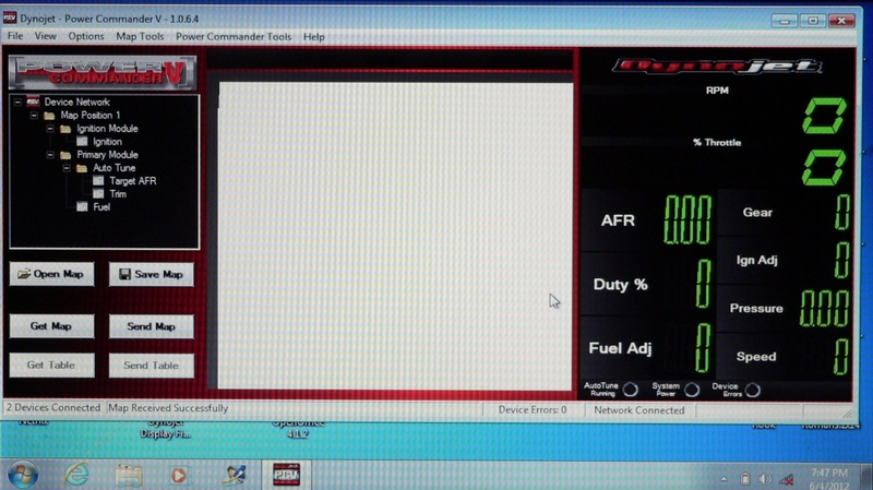
Gauge Panel Various data channels are displayed on the right hand side of the screen below the Dynojet logo when the PCV is connected to the computer. RPM is the number of revolutions per minute the engine is currently turning at. % Throttle is the percentage the throttle is opened. AFR is the number of parts air that are currently mixing with one part of fuel. Duty % is the percentage of fuel injector capacity that is currently in use. Fuel Adj is the percentage of stock units of fuel that is currently being added or subtracted. Gear is the current gear position of the transmission. Speed is the the speed in mph that the wheel is currently turning. Depending on what devices and auxiliary sensors are in your network and how the PCV is configured, you may have more or fewer gauge displays than this.

Indicators There are three indicators below the gauge display, Auto Tune Running will light up when Auto Tune is sampling exhaust. System Power will light up any time the engine runs and Device Errors will light up when an error has occurred with a device in the network.

Status Bar The grey bar at the bottom of the software screen has several boxes to give alerts of what is happening with the system.


Accessing Map Files From Your Computer
You will need to have a PCV map file on your computer desktop to access it. You may get a map file from powercommander.com or ask for a map from a tuner. The computer does not need to be connected to the PCV yet but it may be if you wish.

1. Retrieve the map file you wish to load to the PCV from where the map file is stored on your computer. Place it on the desktop. The map file name must end in the extension .pvm in order for it to be accessed by the PCV software. If the file does not end in .pvm then you must edit this extension at the end of the file name. The icon will change to a Power Commander icon similar to the icon for the software.


2. Double click on the PCV software icon to open the program.


3. The PCV program will open. A Windows Confirm box may come up indicating that the default location for map storage has been changed. If you X out of it it will probably keep coming up or your maps will be sent to your C drive, only. Click the Yes button to have saved maps sent to your desktop where they will be easy to find and safely relocated for storage.


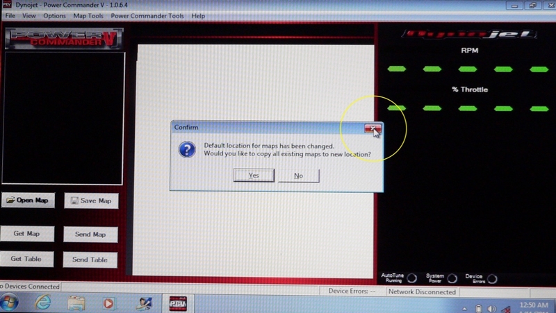
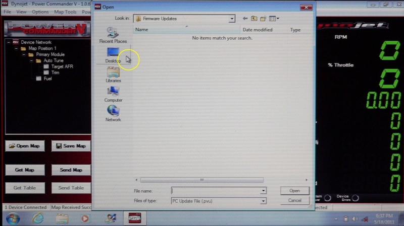
4. Click the Open Map button from, the Control Panel to access the map file you have stored on the desktop.


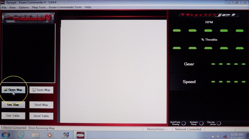
5. A Windows box called Open Map File will open. Click on the icon for the map file you wish to view. The file icon will become highlighted and the information will appear in the search boxes for File Name and Files of Type.


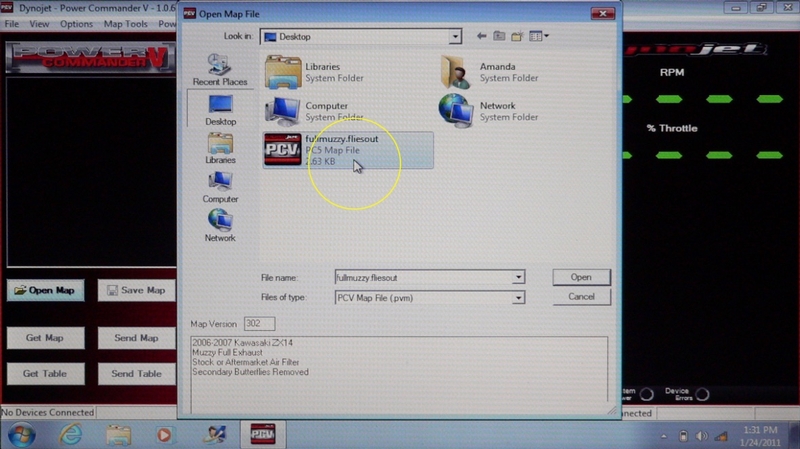
6. Click the Open button in the Open Map File box or click Cancel to close the Open Map File box without opening the selected map.


7. The Table Manager will display the expanded folders for the map. The Map folder is on top and is labeled whatever the opened map is named (in my case, fullmuzzy.fliesout.pvm). Within this folder is the Map Position1 folder. This folder contains the map for toggle switch position 1. The PCV can have a toggle switch connected to it to select between two maps stored in the PCV. If there was a map for toggle switch position 2, you would see a folder for that map as well. Within the Map Switch Position folder is the Primary Module folder. This folder is for the PCV. If there were other devices connected to the PCV, there would also be folders for them inside the Map Switch Position folder. Inside the Primary Module folder is the Fuel folder which holds the fuel map you wish to view.

You may reduce the display of folders by clicking the - symbol to the left of the folder. The - symbol will become a + which can be clicked to expand the display again.

You will notice that the Save Map button in the Control Panel is now activated as well as the Open Map button.

Click the Fuel icon in the Table Manager to view the fuel table for the map you have open.


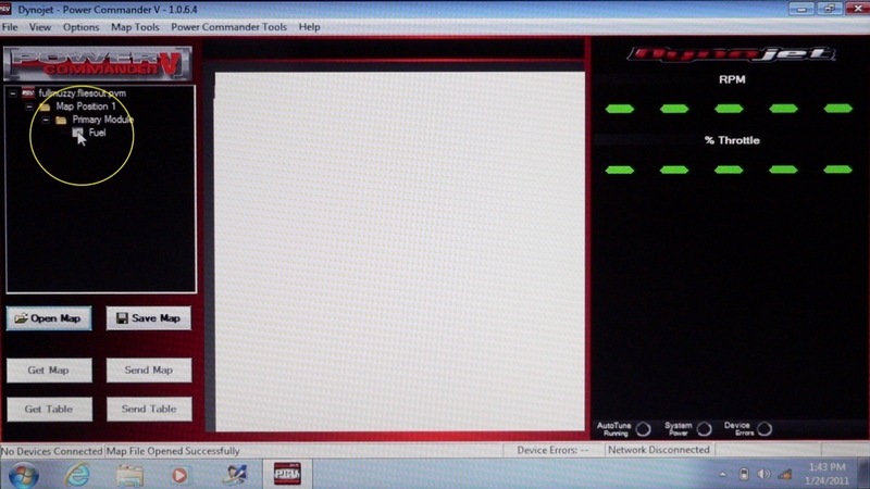
8. The fuel table will open in the Table Window at the center of the PCV software display. Above the fuel table is a notation indicating that this table is for map switch position 1 fuel map cylinders 1, 2, 3 and 4 and for gears 1 through 6. It is possible to have separate maps for each cylinder and each gear when advanced settings are used.

The fuel table is a matrix of throttle position percentage columns and engine rpm rows. Each cell of the matrix has a number that indicates the percentage of stock units of fuel that the map adds or subtracts from the units in the stock fuel table in the ECU (see step 10 of AFR TUNING WITH AUTOTUNE for more info on difference between stock fuel mapping and Dynojet fuel mapping). If there is a minus sign (-) with the number, it indicates the percentage of the stock fueling subtracted (i.e. -10 means 10% of stock fuel is subtracted). If there is just a number, it indicates the percentage of stock fueling that is added (i.e. 10 means 10% of stock fuel is added). If there is a 0 in the cell, that means the fueling in the ECU is unchanged. View the fuel table to understand the following example. The fullmuzzy.fliesout map subtracts 3% of stock fueling at 1500 rpm when the throttle is 2 percent open (the number, -3 is in the 1500 rpm/2 tp cell). At 5000 rpm and 40 percent throttle, the map adds 10% of the stock fueling (10 is in the 5000 rpm/40 tp cell).

The entire fuel table may be viewed by using the up/down arrows to or clicking in the scrolling bar to the right of the Table Window. The map could also be saved to your computer by clicking the Save Map button in the Control Panel but this is not necessary because the map is already on the desktop.

Go to File in the Menu Bar and click Close Map File (see step 20) to close the map file you currently have opened.


Loading Maps
9. In order to load maps and for all other functions of the software to be activated, the software must interact with the PCV. Pull out rubber plug and connect the usb cable to the PCV. Plug the other end of the cable into the usb port on your computer. The power indicator light on the PCV will remain lit with the PCV powered off of the computer.


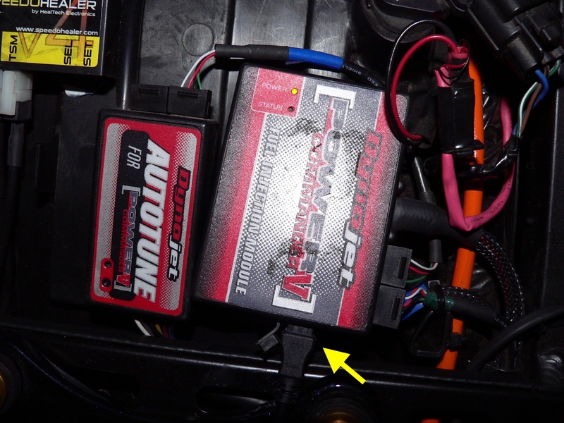
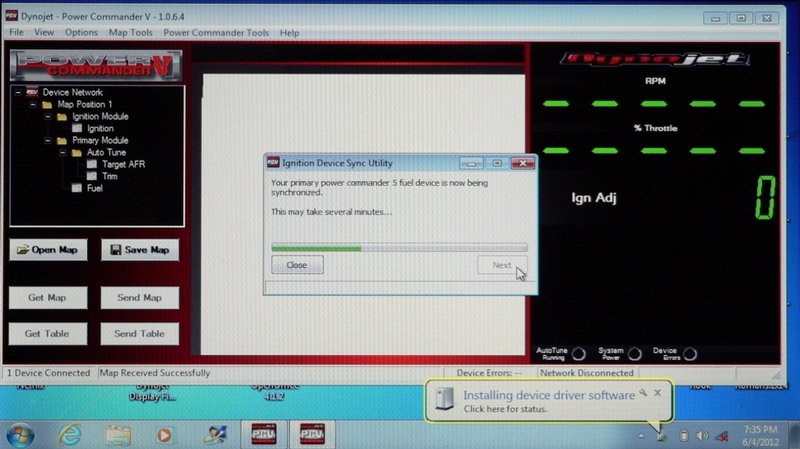
10. A Windows message box will pop up indicating a device driver is being automatically installed to your computer. This will take about one minute.


11. X out of the box that appears when the device driver has been installed from the PCV to your computer. The Get Map button in the Control Panel will be activated when the computer is linked to the PCV. There will be additional gauge displays in the Gauge Panel on the right of the screen.


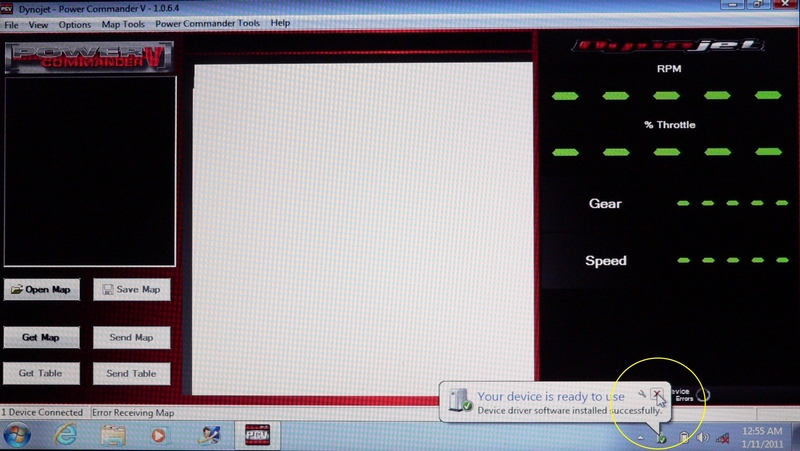
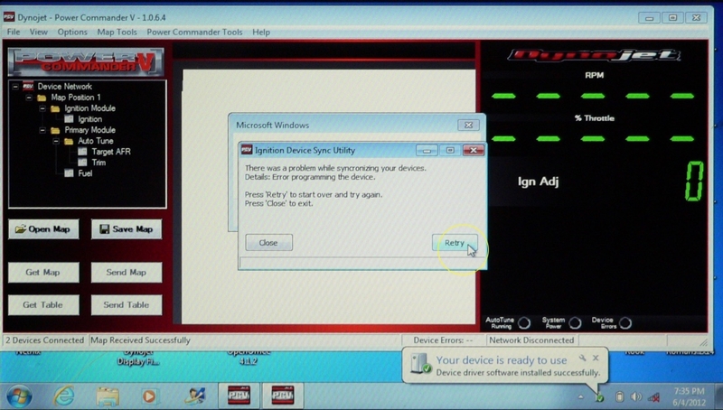
12. Minimize the PCV software to view the desktop. If you see the box shown in the picture below, maximize the PCV software and close it. Click Restart Now in the Microsoft Windows box to apply changes required by the installation of the device driver. Any time you find this box on your desktop after exiting the PCV software, you should click Restart Now before shutting down the computer to avoid unnecessary reboots when you turn your computer back on.


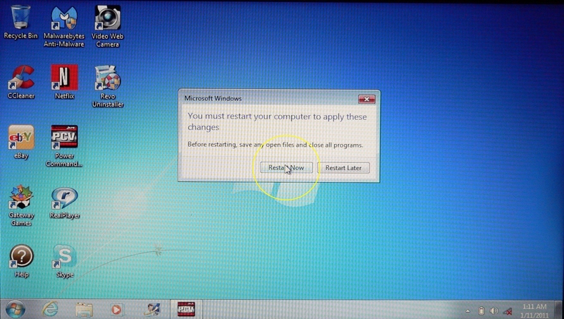
13. When the computer restarts, open the PCV software as described in steps 2 and 3. The dashes in the RPM, % Throttle, Gear and Speed displays in the Gauge Panel will now be 0s and there will be a display for Duty %. If Autotune is connected to the PCV, there will also be an AFR and Fuel adjustment display. If there is a map stored in the Power Commander, it may automatically open identified as Device Network in the map box on the left.


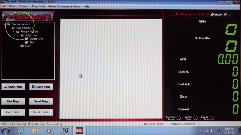
14. Click the Get Map button in the Control Panel. This will only open the map that is stored in the Power Commander and the map file will always be identified as Device Network. Get Map will not allow you to access maps stored on your computer. If you had a map from your computer open for viewing or editing, it would close and the stored map would open when you click Get Map.


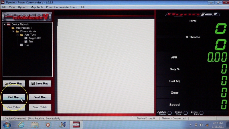
15. Putting a new map into the PCV will erase the old map. If you are going to change the map stored in your PCV, it is very important that you save a copy of the previous one to your desktop first. The default settings of Map Tools should automatically do this for you (see step 23) but I suggest getting in the habit of saving replaced maps manually and checking that they are saved before replacing it.

Click Save Map in the Control Panel.


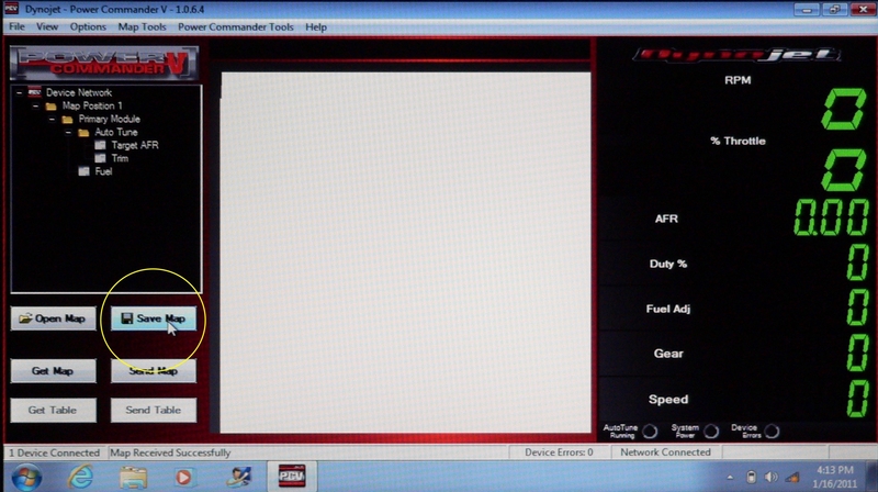
16. The Windows Save As box will open showing all maps already on the desktop. I have the Muzzy full system/flies out map on my desktop and waiting to be loaded after I save the map that is in the PCV. Click the File name text box and enter whatever you wish to name the current map file. I have named the current map m4slips.pvm

Click the Save button and the map in the PCV is saved to the desktop.

X out of the Save as box.


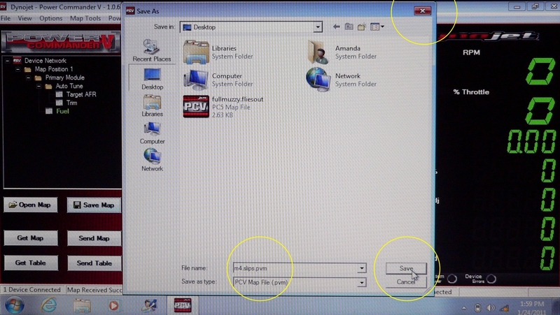
17. Minimize the PCV software to view the desktop. If the map file in the PCV is visible on the desktop, it is now saved. The map you wish to load to the PCV is still located on the desktop as well.

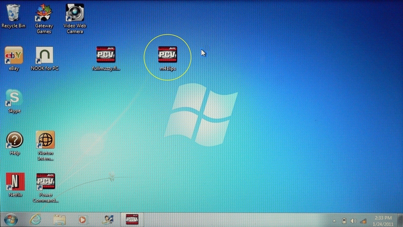
Un-minimize the PCV software again.

18. Follow steps 4 through 7 for opening the map that you wish to load to the PCV from the desktop. In this case, it is fullmuzzy.fliesout.pvm The new map opens and its folders will be expanded in the Table Manager of the PCV software. In the picture below, you also see a folder for Auto Tune because I have Auto Tune connected to my PCV.

Follow step 8 to view the fuel table of the new map.

The new map is opened in the PCV software but it is not yet loaded to the PCV. The current map is saved on the desktop but it remains loaded in the PCV until the new map is loaded. You may click on the Get Map button to view the current map. You may also click Open Map to compare the new map or any other map you have on the desktop.

19. With the current map saved and the new map opened, Click Send Map in the Control Panel. This will load the map that is opened to the PCV. The new map is loaded to and the old map is erased from the PCV. The new map folders will appear in the Table Manager. The map currently loaded to the PCV is always labeled, Device Network.

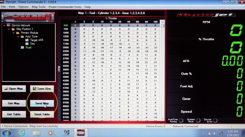
The Get Table button in the Control Panel is used to bring a table from the PCV to the laptop. The Send Table button sends a single table to the PCV from the laptop rather than the entire map. The use of these buttons as well as information on related features of the PCV are covered in AFR Tuning with Auto Tune.

To briefly recap:
To view the map currently in the PCV: Get Map > Fuel
To view a map the is on the desktop: Open Map > select the map icon > Open > Fuel
To save the map currently in the PCV: Get Map > Save Map > name the map > Save
To load a new map to the PCV: Open Map > select the map icon > Open > Send Map


X out of the PCV software.

Functions and Settings of Power Commander 5 v 1.0.6.4
The computer must be connected to the PCV in order to activate all functions of the software. Follow steps 9 through 13 to open the software. The device driver may need to be installed again (steps 10, 11 and 12).

20. Go to the Menu Bar of the PCV software and click File. A menu will drop down with 6 selections. Click Open Recent to open a list of maps that have been recently opened. If you double click on a map from the Recently Opened list, you can navigate to that map in the same manner as you did when you clicked the Open Map button in steps 4-7. You may remove all recently viewed maps from the list by clicking Clear All Recent Files. Open Map, Get Map and Save Map do exactly the same thing as the buttons in the Control Panel with those names (steps 4 through 7, step 14 and steps 15 through 17). Clicking Import PC3USB Map (.djm) which will reformat a PC3 map and open it for use in PCV. Clicking Close Map will close the map file currently open. Clicking Exit will close the PCV software.


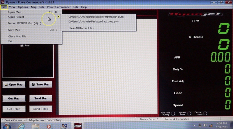
21. Next go to View in the Menu Bar. The menu that open contains three selections.

Cick on Show Map Notes to open a text box at the bottom of the map table window. When this feature is activated with ta map opened, you may see previous notes about the map and you can type your own notes. Click Hide Map Notes.

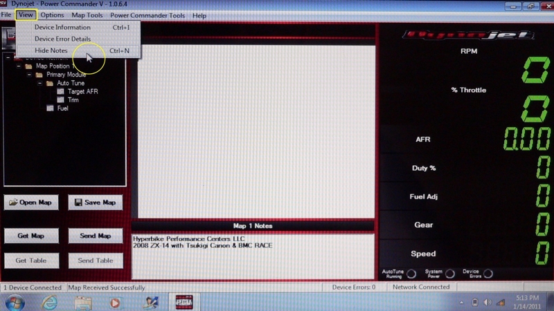
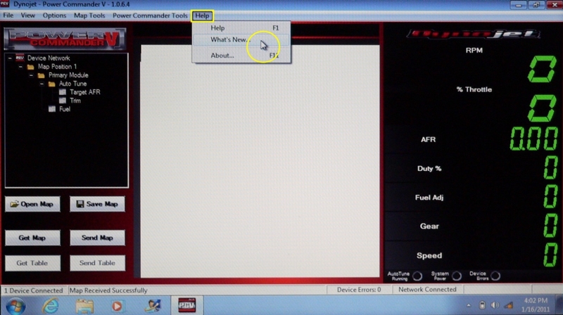
Click on Device Information to view an info box of data and specs about the Power Commander V module in your bike. X out of the info box.

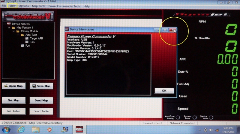
Click on View in the Menu Bar and click on Device Error Details to view info about errors that have occurred with your PCV. X out of the Device Errors information box.


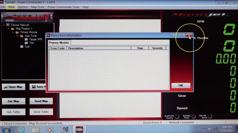
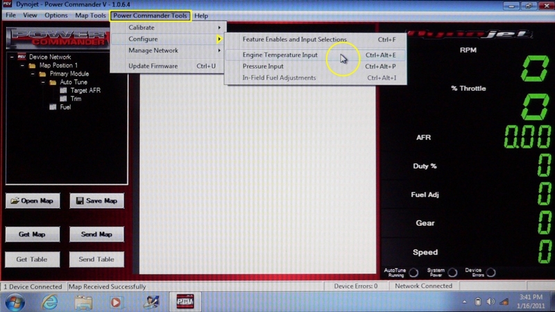
22. Click Options in the Menu Bar. Click Environment Options in the menu that appears.


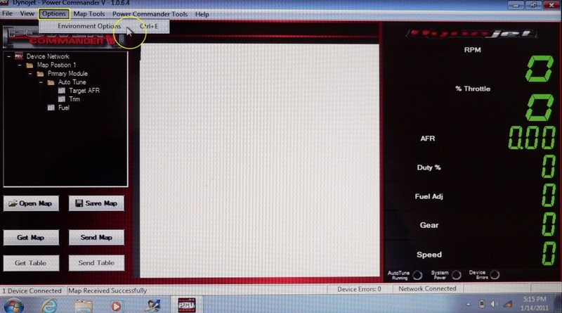
23. A box will appear with various options for the Power Commander functions.

Retrieve device map upon connection will make the map in the PCV open automatically as soon as the power commander is connected to the computer with the PCV software running.

Show ignition tables even if Power Commander is not ignition capable will allow an ordinary PCV to display the ignition folder in the Table Manager and view ignition tables in the Table Window as though it was a PCV+Ignition (PCV+Ignition is a more recent product than the PC5 I own) or if there is a Dynojet Ignition Module in the network. The ignition table will contain all zeroes if the The PCV network is not ignition capable.

Show Auto tune tables even if Power Commander is not auto tune enabled will allow Target AFR and Trim tables to be selected in the Table Manager so that they can be viewed in the Table Window even if there is no Auto Tune connected and enabled (my bike has Auto Tune so you see the selections in the Table Manager). If Auto Tune is not connected and enabled, the target AFR table could be viewed but trims cannot be generated so the trim table will be filled with zeroes.

**To ensure that maps are not accidentally deleted, I recommend that one of the following two preferences be enabled.

Create backup map file upon device connection automatically copies the map in the PCV to your documents folder as soon as the PCV is connected to the computer with the PCV software running.

Create backup map file upon sending map to device automatically copies the map in the PCV to your documents folder as soon as a map is sent to replace it.

Table Cell Tracer Enabled highlights the map cell that the current rpm and throttle position occupy. This is so that you can easily determine in real time what point in the map the engine is running. Duration (sec) determines the length of time cell tracer will be visible.

Software Preferences > Manually select gauge channels will allow you to select only the gauges that you want to see displayed in the gauge panel. Table row height determines the size of the cells viewed in the Table Window. The Small cell selection allows the largest portion of the table to be visible without scrolling.

Click Defaults and then select Small for Table row height. Click OK.


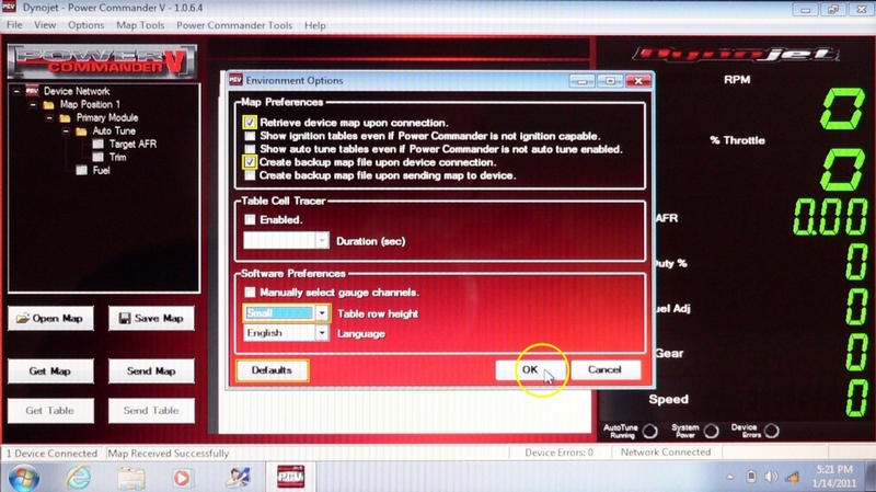
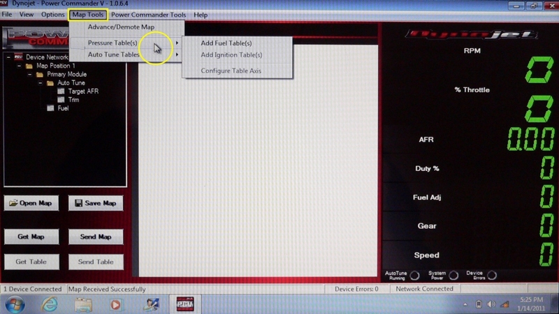
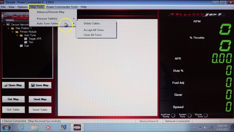
24. Click on Map Tools in the Menu Bar of the PCV software to view a menu of three selections. The first, Advance/Demote Map will open a box where map viewing options of various levels of complexity can be selected.

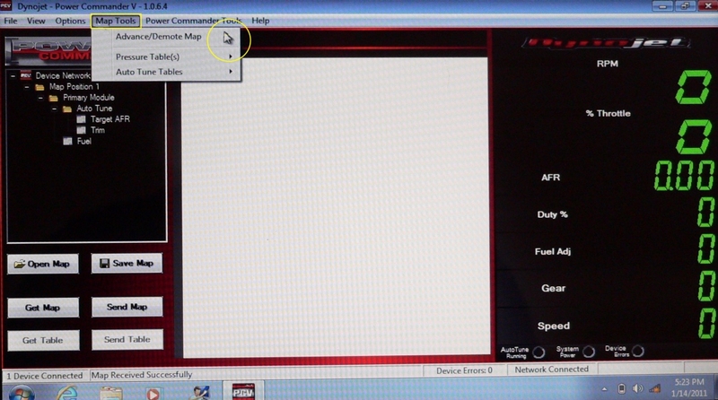
Click the dropdown menu pointer of the first selection, RPM Resolution to select map tables that have rpm cells in increments of 250 rpm or 500 rpm.

Click 250.

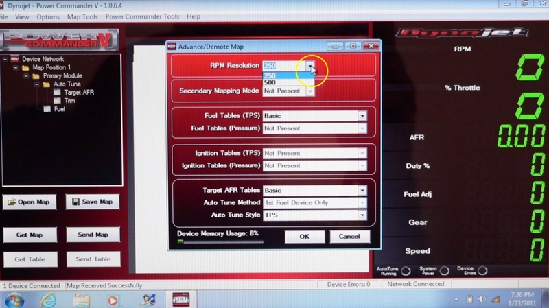
The second selection, Secondary Mapping Mode enables tables from a secondary fuel module to be viewed and/or edited. A secondary fuel module is for engines with eight injectors such as the Hayabusa. Secondary Mapping Mode is Not Present because my PC5 did not have the firmware update at the time a making this tutorial.

Click the dropdown menu pointer for Fuel Tables (TPS) to select from four options. Basic will allow one fuel table for all cylinders and all gears to be opened and viewed as shown in steps 7 and 8. Cylinder Advanced will create folders in the Table Manager display for separate mapping of each cylinder. Gear Advanced will create folders in the Table Manager display for separate mapping of each gear. Cylinder and Gear Advanced will create folders in the Table Manager display for separate mapping of each cylinder and each gear.

Click Basic.

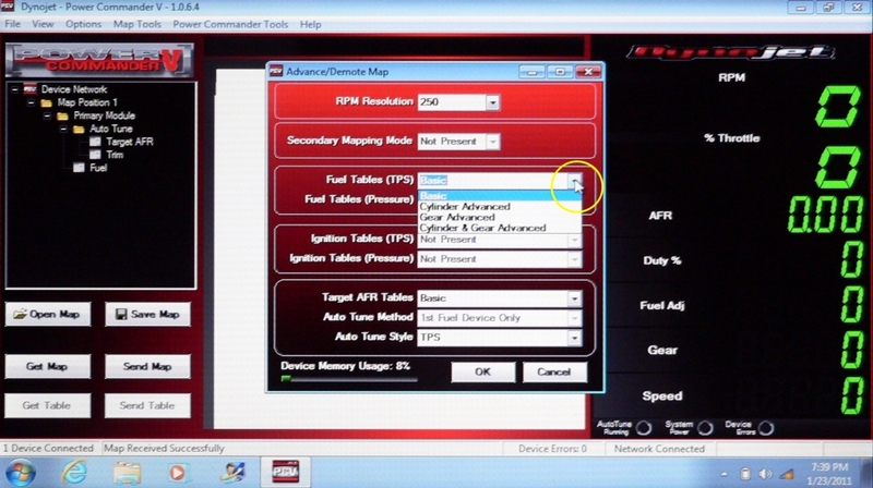
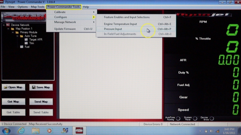
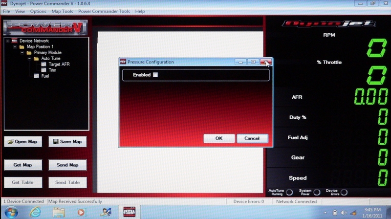
The Fuel Tables (Pressure) is Not Present because my PC5 did not have the firmware update at the time a making this tutorial. Also, this function requires a mass air pressure sensor and auxiliary wiring to be connected to the PCV. Mass air pressure input is useful for tuning turbo applications. I assume the fuel table selections are the same for Pressure as they are for TPS.

Ignition Tables (TPS) is Not Present because my PC5 did not have the firmware update at the time a making this tutorial. These selections are for PCV+Ignition modules or when an Ignition Module when it is connected to an ordinary PCV. The selections for Ignition Tables are the same as they are for Fuel Tables (per cylinder, per gear or per cylinder and gear).

Ignition Tables (Pressure) is Not Present because my PC5 did not have the firmware update at the time a making this tutorial. This feature has the same selections for mapping per cylinder and gear as Ignition Tables (TPS) but the PCV must be equipped with a mass air pressure sensor which is normally only done for turbo bikes.

Target AFR Tables allows separate AFR tables to be created for different gears and cylinders. Basic is the only selection available with the settings I have previously recommended.

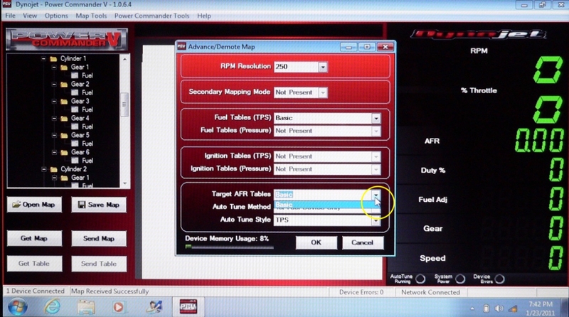
The Auto Tune Method selections would apply to networks with a secondary module for eight injectors. This feature is Not Present because my PC5 did not have the firmware update at the time a making this tutorial.


* Last updated by: Rook on 3/2/2018 @ 7:43 PM *


'08 MIDNIGHT SAPPHIRE BLUE Now Deceased

Link | Top | Bottom

Rook


Rook's Gravatar

Joined: 03/28/09

Posts: 20579

RE: How To Load Maps and Overview of Power Commander 5 v1.0.6.4
07/23/16 11:59 PM

Auto Tune Style selects for tuning via throttle position or mass air pressure. With the previously recommended settings, only one selection, TPS, is available. This would mean that Autotune tables are configured with a throttle % axis. If Fuel Tables (Pressure) was enabled there probably would be a selection for creating Auto Tune tables with a psi axis.

The Advance/Demote Map box also contains a bar indicator for Device Memory Usage. Working with advanced tables will use more of the devices memory capacity.

Click OK to accept changes or Cancel to close the Advance /Demote Map box without changing the previous settings. X out of the Advance/Demote Map box.


25. Click on Map Tools in the Menu Bar of the PCV software and go to Pressure Tables, to open a menu. Bikes with turbo chargers are best tuned by psi of forced induction rather than air/fuel ratios alone. These three selections concern mapping data for air pressure that may be sent to the PCV by auxiliary wiring and sensors. Add Fuel Tables, Add Ignition Tables and Configure Table Axis are clicked to make mapping changes based on readings from a mass air pressure sensor. Unfortunately, I can’t give much more info about this presently but you know it’s there.


26. Auto Tune Tables will open a menu with three items. Delete all Tables will clear the AFR table and fuel trims table currently stored in the PCV. Accept All Trims will accept the adjustments currently suggested to achieve the air/fuel ratios in the AFR table. Clear All Trims will eliminate the current suggested fueling adjustments but retain the AFR table. For complete instruction on using Auto Tune, refer to AutoTune Basics.


27. Click on Power Commander Tools in the Menu Bar of the PCV software. Go to Calibrate and click on Throttle Position.

A box will open to calibrate the Power Commander to the bike’s throttle position sensor. First make sure the minimum and maximum values for the TPS voltage are correct. According to DJ, the minimum voltage for the Gen1 ZX-14should be 1.100 If it is not, click and drag to highlight the Minimum Voltage text box and type in 1.100 The maximum voltage for the Gen1 should be 3.887 if it is not, click and drag the Maximum Voltage text box and type in, 3.887 (for Gen2 ZX-14R, Dj specs min V .630 and max V 3.800)

DO NOT click Reset. Click OK.


Verify that the engine is thoroughly warm and running at operating temperature. You will see the voltage of the throttle sensor displayed in the gray Sensor Voltage box. The number in the grey Sensor Voltage display will fluctuate with the engine running but it should indicate very close to the minimum voltage value that was manually input. If it does not, you may choose to capture the minimum voltage by clicking the pointer to the left of the sensor voltage display.

Again, DO NOT click Reset. Click OK.

I presume the maximum voltage may be captured with the pointer on the right but you would also need to run the engine at or near peak rpm to reach max voltage.


If the number in the % Throttle display of the Gauge Panel is 0 when the engine is warm and the throttle is closed, your throttle position calibration does not require adjustment. Open the throttle a little and view the % Throttle gauge to verify that the % Throttle gauge is functioning.

If the % Throttle display is indicating something other than 0 when the engine is warm and the throttle is closed, you will need to calibrate the TPS by doing the following:

Verify that the engine is thoroughly warmed and running at operating temperature.

Click the Reset button.

With the motor running, quickly open the throttle to the stop and then close it. Do this quickly to avoid prolonged over revving of the engine or hesitation between the full open and full closed positions of the throttle grip.

Click OK.

Check that the % Throttle gauge indicates 0% when closed and functions normally when the throttle is partially opened. You may check the % Throttle calibration of full throttle with the warm engine shut down to avoid over revving. The % Throttle gauge should indicate 97~100% with the grip open to the stop.

The LCD-200 (See LCD-200 Setup and Functions, steps 77 through 80) may also be used to calibrate throttle position.


28. If you will be using a POD-300, LCD-200 or Ignition Module for data logging or real time wheel speed display, you will need to get the speedometer reading into the PCV. Your speed sensor wire will need to be tapped and connected to the Power Commander in order for the signal to be calibrated. If you will not be data logging or do not require a real time display of wheel speed, you do not need to calibrate the speed input.

Click on Power Commander Tools in the Menu Bar of the PCV software. Go to Calibrate and click on Speed Input.

The Speed Calibration box will open to calibrate your speedometer to the Power Commander.

Provided the wire is connected from the stock speed sensor to the Power Commander and the speed input is calibrated, accurate wheel speed will show in the Current Speed window of the Speed Calibration box as it will on a real time engine parameters device. The frequency of the speed sensor will be displayed in the Sensor Frequency (Hz) box. The Target Speed box is used to input the speed you will match (GPS recommended over stock speedometer) to do a live calibration of the PCV wheel speed. The Calibrate button is used to lock in on the chosen target speed.

A Power Commander code called a scalar may be used to calibrate wheel speed instead of doing a live calibration. The scalar code selects a +/- % adjustment that Dynojet has predetermined to display corrected wheel speed for a variety of stock speed error, gearing and tire diameter combinations. You simply enter the code to Scalar box.

The OK button is used to accept the live calibration or the scalar code. The Cancel button is used to close the Speed Calibration box without changing the previous settings.

The complete process of calibrating speed and connection of the speed input wire will be discussed in a future tutorial. The LCD-200 (See LCD-200 Setup and Functions, steps 81 through 86) may also be used to calibrate wheel speed.

X out of the Speed Calibration box.


29. Gear position can also be useful when data logging and tuning. Go to the Menu Bar of the PCV software and click on Power Commander Tools. Go to Calibrate and click on Gear Position.

The Gear Calibration box will open. The white boxes normally are blank until the gear positions are calibrated with a wire being connected from the gear position sensor to the PCV. The values in the white boxes below were given to me by a Dj tech a few years back. These values represent the engine rpm and wheel speed for each Gen1 ZX-14 gear with 17/45 sprockets and a 190/55 tire. The PCV calculates gear ratio from this information and displays it in the grey Gear Ratio box. The gear position is displayed in the grey Gear box. In the Source box, you may select from using Voltage if an analogue gear indicator is used to determine gear (requires wire connection from analogue gear indicator to PCV) or Gear Ratio if the engine and wheel speeds are used to determine gear. Either source will require accurate wheel speed calibration be completed first (step 28 of this tutorial). The other ten buttons and the complete process of gear position calibration will be discussed in a future tutorial.

The LCD-200 (See LCD-200 Setup and Functions, steps 87 through 92) may also be used to calibrate gear position.

X out of the Gear Calibration box.

30. Go to the Menu Bar of the PCV software and click on Power Commander Tools. Go to Configure and click on Feature Enables and Input Selections.

The Feature Selections box will open. The features of the Power Commander that are listed in the Feature column may be enabled or disabled by clicking the check box in the on/off column to the right of the feature. A wire may be connected to the PCV to switch between two maps, to use a quick shifter, or to use autotune. Clicking the dropdown pointer for Map Switch, Quickshifter or Auto Tune allows you to select Switch Input 1 or switch Input 2 according to which wire connection hole you use to connect that feature’s wire to the PCV. The other features do not have a switch input selection because those features do not require auxiliary wiring.

Map Switch

Map Switch allows you use a switch to change between two maps stored in the PCV. The Configure button for Map Switch is not active because PC5 firmware was not updated at the time this tutorial was created.

Quick Shifter Configuration

Go to Quick Shifter and click on Configure. The Quick Shifter Configuration box will open.

Click the Mode dropdown pointer to view the menu. If you are using a quikshifter, select from Single Time or Gear Dependent. Single Time means the same kill time is used for all shifts. Gear dependent means you may choose a different kill time for each gear shift.

Click the Switch Style dropdown pointer to view the menu. Normally Closed means the quickshifter pressure sensor switch on the shift rod is closed at rest and opens when a shift is made. Normally Open means the pressure sensor switch on the shift rod is open at rest and closes when a shift is made. Most pressure sensor switches are normally open. Check with the quickshifter manufacturer for open/closed status of the pressure sensor switch when using GP shift.

Click in the Minimum RPM box to type the minimum rpm you want the quickshifter to be enabled.

Click in the Shift Interval box to type the shift interval of your choice. The shift interval is the minimum amount of time between shifts. If two shifts occur in less time than the chosen shift interval (such as an accidental upshift), the second shift will be ignored.

Click the Kill Mode dropdown pointer to view the menu. Select Kill Fuel Only to eliminate fuel during the kill time. Select Kill Ignition Only to eliminate ignition during the kill time. Select Kill Fuel and Ignition to eliminate both fuel and ignition during the kill time.

The lower half of the Quick Shifter Configuration box contains programmed kill times for each gear. Click in the box for each gear shift and type the kill time you want to have for that gear shift. Kill times entered are expressed in milliseconds.

Click OK to accept the present data entered in the Quick Shifter Configuration box or click Cancel to close the window without changes.

X out of the Quick Shifter Configuration box.

Accel Pump Configuration

The Accel Pump feature adds extra fuel when the throttle is opened rapidly.

Go to Accel Pump and click on Configure. The Accel Pump Configuration box will open.

The grey % Throttle box displays whatever percentage the throttle is currently open. The % Delta Throttle displays the throttle position Accel Pump is programmed to be activated.

Click in the Trigger (% Delta Throttle) box and enter a number between 1 and 100. 1 is most sensitive (most likely to trigger the accel pump feature), 100 is least sensitive.

Click in the Duration (Revs) text box to enter the number of engine revolutions you would like extra fuel to be added when the acel pump is activated.

Click in the Fuel Adjustment (%) text box to enter the percentage of extra fuel you would like to have added when Accel Pump is activated.

The Capture button may be used in conjunction with live application of throttle to select a delta throttle position rather than inputting a value in the Trigger box.

Click OK to accept the present data entered in the Accel Pump Configuration box or click Cancel to close the window without changes.

X out of the Accel Pump Configuration box.

Start Fuel Configuration

The Startup Fuel feature allows you to add or subtract fuel for a chosen period of time when the engine is started.

Go to Startup Fuel and click on Configure. The Startup Fuel Configuration box will open.

Click the Mode dropdown pointer to view the menu. Run Time is a specified period of time the startup fuel will be adjusted. Engine Temperature is a specified engine temperature at which the startup fuel adjustment will shut off. Select either Run Time (sec) or Engine Temperature.

Click in the Run Time (sec) or Engine Temperature text box. According to whichever mode you selected, enter either the number of seconds you wish Startup Fuel to be activated or the engine temperature at which you wish Startup Fuel to shut off.

Click in the Add Fuel (%) text box. Enter the percentage of fuel you want added while Startup Fuel is activated. To subtract fuel while Startup Fuel is activated, type a minus sign (-) before the number you enter (i.e., -5).

Click OK to accept the present data entered in the Startup Fuel Configuration box or click Cancel to close the window without changes.

X out of the Startup Fuel Configuration box.

Rev Xtend

Rev Extend allows allows the engine to turn at a chosen rpm above the factory red line before the rev limiter is activated. This feature does not work with the ZX-14 unless an Ignition Module is in the PCV network. Consult with DJ tech support for more information.

Go to Rev Xtend and click on Configure. The Rev Xtend Configuration box will open.

The Rev Limit box shows the factory rev limit for the Gen1 ZX-14 which is 10,900 rpm. DJ tech support will provide a code called a key that may be input for any rev limit desired. The key is typed into the text box and the Load Key button would is clicked to accept the code associated with the new rev limit.

X out of the Rev Xtend Configuration box.

Auto Tune Switch

The Auto Tune Switch feature (not to be confused with Auto Tune, directly below) disables Auto Tune until the map switch is activated. The Configure button for Auto Tune Switch is not active because PC5 firmware was not updated at the time this tutorial was created.

Auto Tune

Go to Auto Tune and click on Configure. The Auto Tune Configuration box will open.

If you would like the engine to run for a minimum time before Auto Tune becomes activated, click to check the Require Run Time box.

Click in the Minimum Run Time (sec) text box to enter the number of seconds after the engine is started that you want Auto Tune to become activated. AutoTune is factory set to activate in no less than 20 seconds.


If you would like the engine to reach a particular temperature before Auto Tune is activated, click to check the Require Engine Temp box.

Click in the Minimum Temp text box to enter the temperature that the engine must be reach before Auto Tune is activated.

Click the Max Enrichment Trim (%) text box to enter the greatest addition of fuel you want auto tune to be able to suggest in the fuel trims table.

Click the Max Enleanment Trim (%) text box to enter the greatest reduction of fuel you want auto tune to be able to adjust in the fuel trims table.

The Number of O2 Sensors selection box allows you to set the number of O2 sensors that the PCV was equipped with from the factory. Normally AutoTune only has one but some setups have multiple O2 sensors.

Click OK to accept the present data entered in the Auto Tune Configuration box or click Cancel to close the window without changes.

X out of the Auto Tune Configuration box.

Click OK to accept the present data entered in the Feature Selections box or click Cancel to close the window without changes.

X out of the Feature Selections box.


31. Go to the Menu Bar of the PCV software and click on Power Commander Tools. Go to Configure and click on Engine Temperature Input.

The Engine Temperature Configuration box will open. The engine temperature can be monitored by the PCV via a wire tap to the bike’s engine temperature sensor or by an aftermarket temperature sensor.

To enable the the engine temperature input, check the Enable box.

Click the Source dropdown pointer and select Analog Voltage.

Use the dropdown pointer to select the number of columns you wish to have displayed.

Enter the voltages and display values of your sensor (i.e., 0.5V=0 F, 4.5V=200 F).

Click OK to accept the present data entered in the Engine Temperature Configuration box or click Cancel to close the window without changes.

X out of the Engine Temperature Configuration box.


32. A pressure sensor may be installed and wired to the PCV to monitor air box pressure for turbo applications. Go to the Menu Bar of the PCV software and click on Power Commander Tools. Go to Configure and click on Pressure Input.

The photo below shows the display that comes up on my computer screen. Check the Enabled box to enable pressure data to be sent to the PCV. There may be more data and selections to enter if the PC5 firmware is up to date.

Click OK to accept the present data entered in the Pressure Configuration box or click Cancel to close the window without changes. X out of the Pressure Configuration box.


33. Go to the Menu Bar of the PCV software and click on Power Commander Tools. Go to Configure > In-Field Fuel Adjustments.

The In-Field Fuel Adjustment box opens.

The fueling adjustment is divided into five rpm zones: Low, middle and High with two slope zones which transition from Low to middle and middle to High.

The Low RPM zone will always start at 0 rpm. Click in the Low RPM box to enter the rpm that you want the low zone to end at.

Click the High RPM box to enter the rpm that you want the high zone to start at. The High rpm zone will always continue up to whatever rpm your engine redlines at.

Click the Slope RPM box to enter the number of rpm you desire for transition from one zone to the next. A Slope RPM of 0 will cause an abrupt transition from one zone to the next. Larger Slope RPM values will cause a gradual transition from one zone to the next.

Click and drag the slider controls to select the adjustment you want for Low middle and High RPM zones.

The plot line in the graph serves to indicate the adjustments made with the slider controls. Being that the max rpm on the horizontal axis is 7000, it cannot display the entire rpm range for the ZX-14 engine. You might as well ignore the rpm markings on the graph altogether and refer to the values you entered for Low RPM and High RPM for zone identification.

If you are riding cross country and find yourself at a much different altitude than you ride at home, this utility may be of some use to you. You would certainly want to make adjustments very conservatively and with the use of the AFR gauge. This method of adjusting the fueling is crude compared to the adjustments that can be made with AutoTune. If you have AutoTune, the only reason to use In-Field Fuel Adjustment is if you do not have your laptop along to make adequate fueling adjustments but you do have an LCD or POD-300. If necessary, the POD-300 and LCD-200 can be used to make In-Field Fuel Adjustments without the PC5 software.


When Low, High and Slope RPM are entered and adjustments are selected with the sliders, click Apply.

These changes will be permanently made to the fuel map. Reload the original map to reverse the adjustments.


34. Go to the Menu Bar of the PCV software and click on Power Commander Tools. Go to Manage Network and click on Search For Devices To Add.

An information box will come up for new devices (such as AutoTune, Wideband2 or POD-300) connected into the Power Commander network. Click OK to accept the device into the network. If there are no new devices, X out of the information box.

More complex devices such as an Ignition Module or Secondary Fuel Module will require syncing to the the PC5 and other devices in the network that connect inline with OEM harnesses.

34a. Connect the newly added device to the computer by USB cable. I connected both the newly added device and the PC5 to the computer at the same time (see Ignition Module Install, steps ** through **). You might avoid the error message if you do not connect the PC5 until told to do so in the following steps. I have not tried it that way.

Sync Devices Utility will be in the Manage Network menu if a device requiring synchronization has been added to the network.

Go to the Menu Bar of the PCV software and click on Power Commander Tools.

Go to Manage Network and click on Sync Devices Utility.


34b. The synch data from the new device will load to the Control Center Software. Click Next.


34c. A message box will appear telling you that one of the other devices in the network require syncing to the newly added device.

Click Next to synchronize the device to the newly added one.

The message will change and a progress bar will appear to indicate that the device is being synchronized to the newly added device.

A device driver will also install.


34d. If an error message comes up, it probably is because the device driver did not load fast enough to process the data. Click Retry.


34e. Sync data from the newly added device will reload.

Click Next.


34f. A message will appear telling you to connect your PC5 to the computer. If the PC5 is already connected, click Skip.


34g. A message will appear telling you to connect your Secondary Module to the computer if a Secondary Module exists. Connect the Secondary module if it exists in the network or click Skip.

At the time this tutorial was written, there were no Dynojet devices that require synchronization other than the PC5, Secondary Module and Ignition Module.


34h. Click Finish to complete the device synchronization procedure.

The gauge display may change but this will return to the previously chosen layout when the software is reopened.


35. Go to the Menu Bar of the PCV software and click on Power Commander Tools. Go to Manage Network > Primary Module (PCV). The Remove selection will appear. If you remove it, you will have to do step 27 to search for the PCV and add it to the network in order for it to be recognized by the PCV software.


* Last updated by: Rook on 3/9/2018 @ 3:46 PM *


'08 MIDNIGHT SAPPHIRE BLUE Now Deceased

Link | Top | Bottom

Rook


Rook's Gravatar

Joined: 03/28/09

Posts: 20579

RE: How To Load Maps and Overview of Power Commander 5 v1.0.6.4
07/24/16 12:00 AM

36. Go to the Menu Bar of the PCV software and click on Power Commander Tools. Click on Update Firmware.

The Update Device Firmware box will open listing any devices in the Dynojet network that require firmware updating. Highlight the device you wish to update.

You may click the Show Details button to open a box that will list the firmware updates as they download to the computer.

Click the Update button to connect to powercommander.com

The latest firmware will download automatically indicated by a progress bar. The identity of the update will display in the details box.

Click the Close button to close the Update Device Firmware box.

OR

X out of the Update Device Firmware box to close it without accepting firmware update downloads.

After closing the Update Device Firmware box, a Windows Open box will open so that you can navigate to the location of the downloaded updates file.

I found my updates file on the thumb drive where I store my maps.

Select the updates file and click Open. The firmware of the selected device is updated.


37. Go to the Menu Bar of the PCV software and click on Help. A menu of three items will drop down. Click on Help in the menu.

The internet will open to a Dynojet PCV self help page. There are two links on the left. Click the Welcome to PCV link. There is not really any valuable info here, but the tabs on the upper left are helpful.

If you click the Working with PCV link, you will find many helpful links to brief step by step instruction for all aspects of the PCV software that are covered in this tutorial. Not all are completely accurate so you will have to refer to this tutorial or call Dj tech support for clarification in some situations. The tabs on the upper left are helpful and they are the same on both pages.

Here is the link to Welcome to Power Commander 5.

X out of your internet browser.


38. Go to the Menu Bar of the PCV software and click on Help. Click on What’s New in the menu.

The internet will open to a page that has links to self help information about The latest PCV software. The same tabs that are on the Welcome to PCV and Working with PCV pages (see step 37) are available on this page.


39. Go to the Menu Bar of the PCV software and click on Help. Click on About in the menu.

A box will open that identifies what version of PCV software this is and a link to the Power Commander website.

Click OK to close the box.

Go to File > Close Map File

Go to File > Exit or X out of Power Commander 5 software to close the program.


* Last updated by: Rook on 3/9/2018 @ 4:09 PM *


'08 MIDNIGHT SAPPHIRE BLUE Now Deceased

Link | Top | Bottom

untamed


untamed's Gravatar

Location: RSA

Joined: 08/18/13

Posts: 347

RE: How To Load Maps and Overview of Power Commander 5 v1.0.6.4
07/26/16 11:26 AM

Well done, this is really good and easy to understand info. I wish I had access to something like this when I started with the PCV and autotune.


Life begins at 40.......The fun starts at 240.
Now riding 2014 ohlins ZZR 1400, Z 750, GPZ1100ZX, ZZR1100, Hayabusa, GSXR1000, 2009 ZX14 special edition.

Link | Top | Bottom

Rook


Rook's Gravatar

Joined: 03/28/09

Posts: 20579

RE: How To Load Maps and Overview of Power Commander 5 v1.0.6.4
07/26/16 8:42 PM

Thanks untamed. As mentioned in the intro, much of this info is covered in Dj's self help links. Only thing is some of the illustrations and instructions are incomplete or slightly inaccurate. Maybe they are showing instruction for the PC3 in some cases. This info is not 100% complete either but I tried to explain the basic purpose of everything. When it comes to actually using the functions, there will probably be more info needed. I plan to address certain functions of the software where they pertain to Power Commander perifferals like Map switch, Quikshifter and Auto Tunein future tutorials .


* Last updated by: Rook on 7/26/2016 @ 8:44 PM *


'08 MIDNIGHT SAPPHIRE BLUE Now Deceased

Link | Top | Bottom

Rook


Rook's Gravatar

Joined: 03/28/09

Posts: 20579

RE: How To Load Maps and Overview of Power Commander 5 v1.0.6.4
12/22/16 9:54 PM

reloading photos again. will get it all by new years day


'08 MIDNIGHT SAPPHIRE BLUE Now Deceased

Link | Top | Bottom

projo198


projo198's Gravatar

Joined: 03/13/17

Posts: 102

RE: How To Load Maps and Overview of Power Commander 5 v1.0.6.4
03/21/17 9:49 AM

Man this is great, thank you for taking the time do write this up. My work computer blocks the images but I finally got around to viewing it in a civilian laptop and it is helping a lot. I just installed my PCV last night and am looking forward to figuring this all out.

Link | Top | Bottom

Rook


Rook's Gravatar

Joined: 03/28/09

Posts: 20579

RE: How To Load Maps and Overview of Power Commander 5 v1.0.6.4
03/21/17 7:17 PM

Glad it helps, projo. Make sure you have the most recent firmware uploaded. Many of the settings were not available when I did this tutorial becauase I had old firmware in the PC5. Check out step 36.

I am very curious to know if rev extend can be applied to the Gen1 14. I've always heard this was not possible. Also, the ignition module has a rev extend feature. I will try this summer. If we have rev extend through modules---------I really don't see any reason to get a flash as long as you have AutoTune and the Ignition Module. Ignition is just a matter of who you trust. Romans has told me a lot of people have ignition backwards and that's why you see engines blow up. The 14's upper rev ignition is already close to where it should bee=...or something like that....hope to iron this out with Romans this summer.


'08 MIDNIGHT SAPPHIRE BLUE Now Deceased

Link | Top | Bottom

Rook


Rook's Gravatar

Joined: 03/28/09

Posts: 20579

RE: How To Load Maps and Overview of Power Commander 5 v1.0.6.4
11/14/17 7:01 PM

updating again.


'08 MIDNIGHT SAPPHIRE BLUE Now Deceased

Link | Top | Bottom

Rook


Rook's Gravatar

Joined: 03/28/09

Posts: 20579

RE: How To Load Maps and Overview of Power Commander 5 v1.0.6.4
03/04/18 7:24 AM

updating again again.


'08 MIDNIGHT SAPPHIRE BLUE Now Deceased

Link | Top | Bottom


Welcome to zx14ninjaform.com!
 
New Topic Reply
Next Page

Page: 1

Previous Page

New Post

Please login to post a response.