


Camshaft Tests:
Runout, Cam Wear and Cap Wear
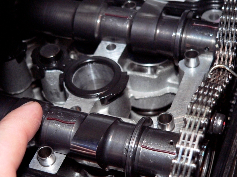
If the camshafts are removed they might as well be tested. The valve clearance check is a good time to to do these three tests. My camshafts were tested at 29,000 miles and there was enough wear on one of them to be worth while taking note of.
Runout
Ideally, a camshaft will be perfectly straight from end to end. A straight camshaft will rotate smoothly in a balanced fashion and a warped shaft will rotate with a wobble. The runout test measures the amount that the camshaft varies from the ideal, perfectly straight rotation that would produce the best operation. There is an acceptable range of “bentness” to a camshaft. Even a brand new camshaft has a specced runout tolerance.
Cam Wear
The cam lobes repeatedly making contact with the lifters causes the lobes to wear down. The lobe becomes shorter with wear. The cam wear test is conducted by simply taking a vey accurate measurement from the tip of the cam lobe to the opposite side of the cam.
Camshaft Cap Wear
The surfaces of the camshaft caps that adjoin the camshaft journals need to be checked for wear also. The space between the caps and the journals is meant to be no larger than what is necessary to hold a film of oil for the camshaft journals to spin on. The space is very small and would be impossible to measure with a feeler gauge. Plastigauge (see below) is used to measure instead of a feeler gauge.
Special Tools
V-Blocks
I was not able to find v-blocks that were narrow enough to fit the journals of the ZX-14 camshafts. The v-blocks that I purchased were a cast and machined iron matched set and cost only five dollars plus nine dollars shipping. The machining looked and felt precise. You can find inexpensive blocks such as these if you search on Amazon and Ebay.
The blocks I got were one and a half inches high. It will not be possible to use v-blocks any shorter than that because the cam lobes will not have enough clearance. I cut a chunk out with a hacksaw to make the blocks about 5/8 inch wide so that the support would fit the journals of the cam shafts. I softened over all edges with 220 sand paper to eliminate any burs that may have been present which would damage the cam shaft journals.
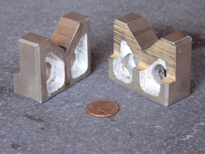
Fishtail blocks would work well to hold a camshaft are but they usually are costly. Although they do not seem to come in matched sets, I would bet that all are machined very close to identical.
I would not hesitate to use two unmatched fishtail blocks from the same maker together for the purpose in this tutorial. Fishtail blocks can be set up on end and the Narrow V (the fishtail) on the base should be thin enough to fit a camshaft journal without doing the extra work of cutting with a hacksaw.
Magnetic Base
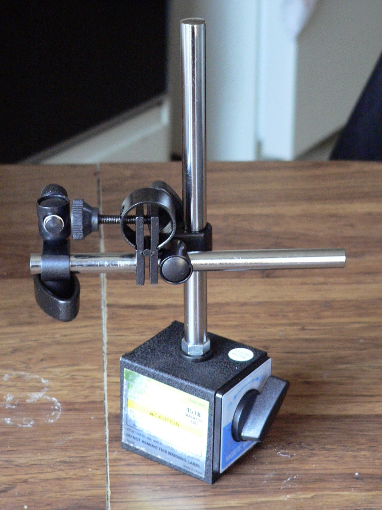
The magnetic base was purchased at Harbor freight for about $11. It has an on/off switch that controls a very powerful magnet that is housed inside of the cube shaped bottom. I did not use the magnetic feature because the base is heavy enough to hold itself in place for the purposes of the runout test. The beam can be adjusted both horizontally and vertically and it may be pivoted 360 degrees. The beam also has a handy spring loaded fine tune screw for height.
Travel Gauge
The travel gauge was purchased at Harbor freight for eight dollars. As is typical of this type of gauge, there is a dial to calibrate the needle to the markings on the face and also a dial to release the face so that it may be turned to calibrate the scales with the needle. The large dial displays travel from .000” to .1” The small dial displays travel from .1 inch to 1 inch.
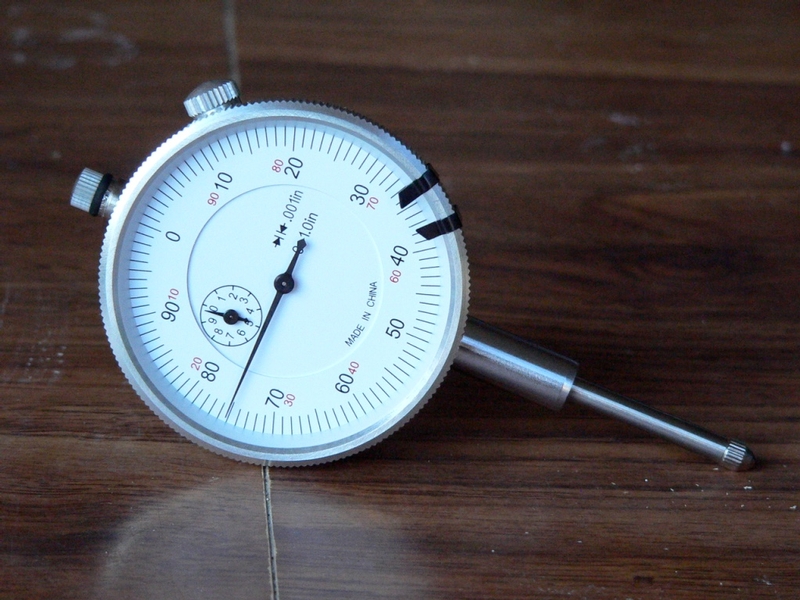
The gauge is initially set with needle at -.075” as shown. The negative value is used to set up the height of the tool in relationship to the circumference that is being measured.
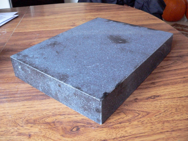
Surface Plane
The surface plane purchased on Ebay from a company called Woodcraft cost $25 which was a great deal. It is marble and comes with a report which claims precision within .001mm/m. The size is 11 7/8” x 9 1/8”. This is barely large enough for the length of the camshafts. I was able to use it by arranging my V blocks on the surface plane from corner to corner.
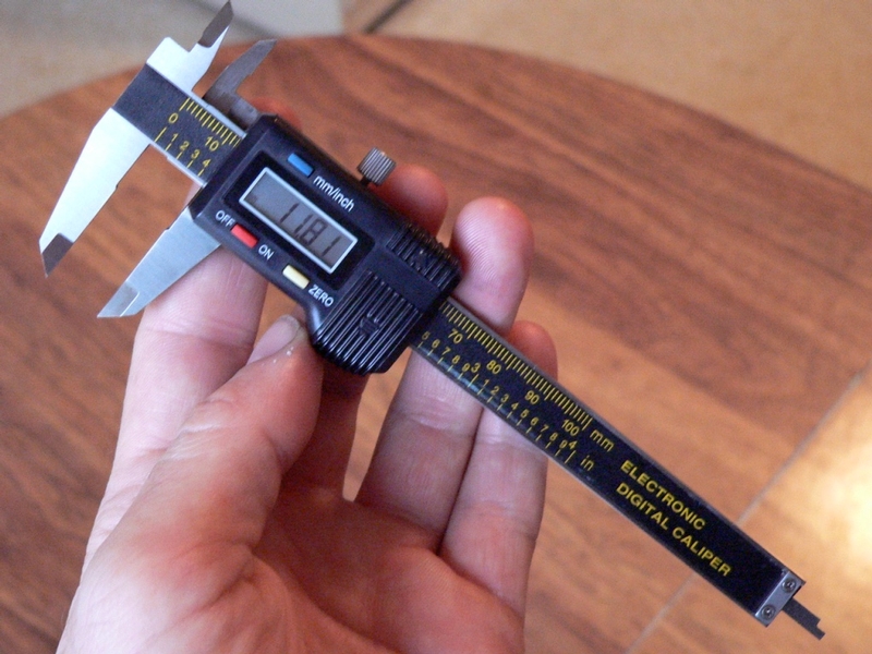
Digital Calipers
The Pittsburg 4” digital calipers was also purchased at Harbor Freight and it cost approximately nine dollars. The calipers measures outside distances as well as inside. the calipers can be calibrated for inches or millimeters. It measures within 1/100th mm or 1/1000 inch and seems to be very accurate when tested with feeler gauge tapes. There is a knack to using the calipers to obtain consistent measurements. A caliper like the one pictured above is easy to use but it will produce a variety of readings based on how parallel or straight it is placed to the axis of measurement and how tight the jaws are closed. I practiced with mine quite a bit and eventually was able to come up with very similar readings over and over. Slide the jaws closed until they touch both sides of the object being measured. If calipers are closed too hard or are placed on the cam crooked, there will be a difference in the readings obtained. Use the tips of the jaws where the edge has been beveled to take the measurement.
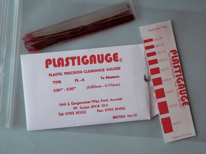
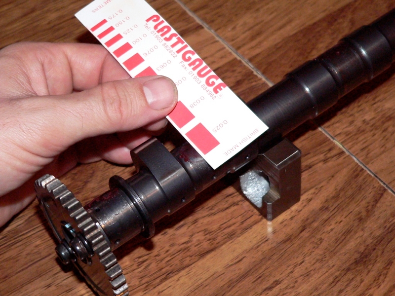
Plastigauge
This material is a thin, waxy rod that is placed between parts which are then installed and torqued as usual to produce the normal clearance between the parts. The parts are then separated again and the width of the compressed film of Plastigauge is measured. The width of the film is referenced on a chart to indicate the clearance between the parts.
Plastigauge should be removed from parts after use but it can cause no harm to the motor if any is left remaining on internal engine parts.
Plastigauge comes in consumer and industrial sized packs and in different weights. The proper weight is PL-A and it is available online at
One small envelope contains 10 strands of Plastigauge which is enough to repeat the camshaft cap wear measurement ten times. The price including shipping was about $12.
There is a less expensive product called Pressgauge. I have not used it. Pressedgauge and Plastigauge are both mentioned in the Service Manual.
Tools:
v-blocks
hacksaw
1” travel gauge
magnetic base or other bracket to hold the travel gauge
surface plane (14” minimum)
caliper measuring tool
5 mm alllen wrench
3/8” drive 5 mm hex key socket
3/8” drive torque wrench
Plastigauge (or Pressgauge)
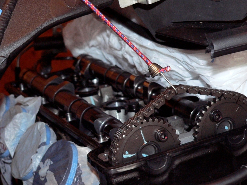
Camshaft Runout
1. Remove the camshafts. (See CAMSHAFT REMOVAL, steps 1 through 8)
2. Wipe oil from camshaft. The V blocks are placed on the surface plane supporting the two outermost camshaft journals. The travel gauge is placed with its piston resting on the center journal.
3. The travel gauge is roughly set to the proper height using the adjustable arm of the magnetic base so that the dial displays 0.
4. Turn the cam shaft to the lowest point in the its rotation. There is an adjustment spring on the arm of the magnetic base which may be used to fine tune the height of the travel gauge. With the shaft turned to it’s lowest point, set the the needle so that it is at 0”.
5. The camshaft is turned in the v blocks and the travel indicated on the gauge is noted.
Be careful to avoid running the travel gauge piston over the oil holes in the camshaft.
Camshaft Runout
Standard: TIR 0.02 mm (0.0008”)
Service Limit: TIR 0.1mm (0.004”)

Cam Wear
6. Place the camshaft on V-blocks.
7. Using a calipers, measure the distance from the top of the cam lobe to the opposite side.
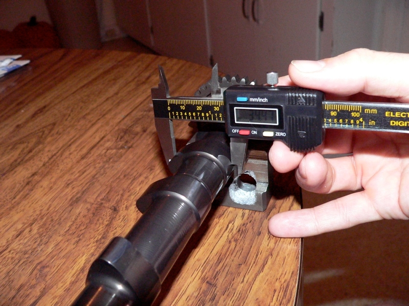
Cam Height
Standard:
Exhaust 34.442 ~ 34.556 mm (1.3560 ~ 1.3605 in.)
Inlet 35.042 ~ 35.156 mm (1.3796 ~ 1.3841 in.)
Service Limit:
Exhaust 34.34 mm (1.352 in.)
Inlet 34.94 mm (1.376 in.)
Camshaft Cap Wear
8. Partially install Camshafts. (see CAMSHAFT REMOVAL, step 10)
9. Apply silicone mold release agent to the surfaces of the cap that adjoin the camshaft
journals.
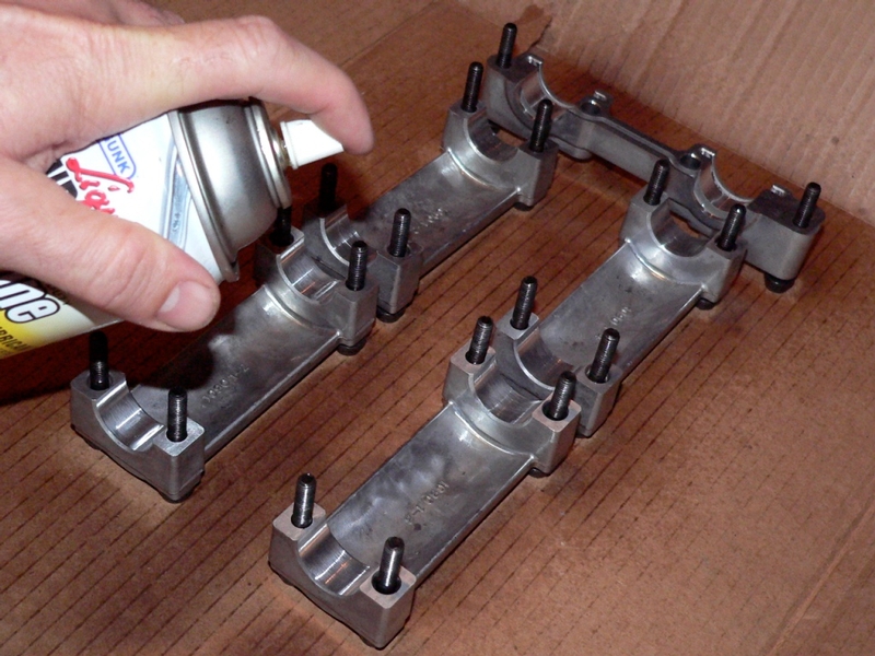
I used a silicone spray, instead of mold release agent.
Apply a thin film of grease to the tops of the journals on both camshafts. Cut the Plastiguage into 10 pieces, approximately 9/16” long.
10. Place a 9/16” piece of Plastigauge on the film of grease on each camshaft journal so that the plastigauge will not fall off. Avoid placing the plastigauge over oilling holes in the camshaft journals.
11. Install camshaft caps. (see CAMSHAFT REMOVAL AND INSTALLATION, steps 11 through 15) Torque the cap bolts to spec, 106 in lbs.
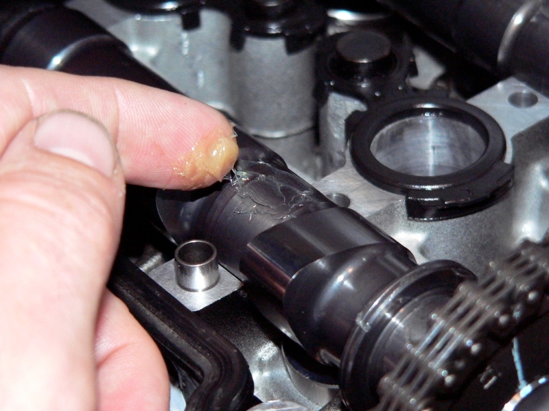
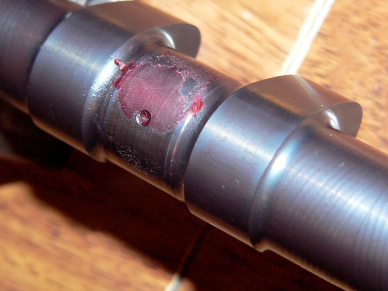
12. Remove the camshaft caps and the camshafts. (see CAMSHAFT REMOVAL AND INSTALLATION, steps 1 through 8).). Using the printed Plastigauge clearance gauge, measure the Plastigauge films left on the camshaft journals.
Camshaft Cap Clearance
Standard: 0.038 ~ 0.081 mm (0.0015 ~ 0.0032 in.)
Service Limit: 0.16 mm (0.0063 in.)
13. Carefully uncover any oil holes that may have gotten Plastigauge in them. Clean
the plastigauge off of the journals using a clean rag and fresh motor oil.
14. If all Camshaft journals show that they are within the service limit, reinstall the
Camshafts. (CAMSHAFT REMOVAL / INSTALLATION, steps 8 through 15).
Camshaft caps and head are made to fit parts. If camshaft caps become worn beyond the service limit, they are supposed to be replaced with new Caps and also a new head which is matched to the caps.
* Last updated by: Rook on 2/1/2018 @ 5:48 PM *